Showing posts with label Electrical Engineering. Show all posts

Thursday, September 29, 2011

Electrical and Electronic Engineer Career Description

There are many similarities though also differences, between electrical and electronics engineering. In earlier years electronics engineering was known as "low-voltage' and electrical engineering as "high-voltage'. This classification is not correct or relevant any more. The difference lies in terms of information associated with electronics engineering and electrical energy that goes together with electrical engineering. With the above-mentioned as basis we can now look at what electrical and electronics engineering exactly are.

Electronic engineering :

Electronic engineering is that branch of engineering that has the specific goal of extending and supplementing the human senses and skills. It has to do with the obtainment, assimilation, control, transmission and distribution of information. Examples of electronic engineering are as follows:


» The use of an infra-red camera to "see" in the dark - an example of obtaining information. Phenomena that cannot be observed by humans, are transformed by electronic technology to observable phenomena.

» The use of computers to solve complicated problems and to assimilate signals assimilation of information.

» The control of mechanical and chemical processes through electronic systems control of information.

» International telephone conversations and video phones - transference of information.

» Mass media such as radio and television distribution of information.


Electrical engineering :


Electrical engineering is a wide field of study, which comprises all aspects of energy systems. It has to do with the generation, distribution and optimal application of electrical energy. Examples of these are:

» Thermic coal power-stations - here chemical energy is transformed to electrical energy - an example of the generation of electrical energy.

» The use of sun cells and wind-chargers to transform wind and sun energy into electrical energy - two examples of alternative ways to generate electrical energy .

» Transmission lines that cross the country, substations and eventually the separation box in a residence - distribution of electrical energy.

Just think for a moment how your day would be during a total power failure - this will give you a good idea of how electrical energy is applied to benefit all people. Even for those who do not have electricity at home it will be easy to see the advantages of electrification.

New technologies such as new materials, super computers, super-wiring and driving electronics are responsible for great innovations / strides in electrical energy techniques.

Electrical and electronic engineers are busy with the fulfilment of a phase (or phases) of the engineering process, especially with relation to the electrical and electronic related disciplines. This process comprises various aspects including studying, problem formulation, setting up specifications, pre-studies and analysis, design, simulation, research, development, testing, realisation, marketing, maintenance of electrical and electronic components, subsystems and systems. Electrical and electronic engineers are not necessarily involved with all the phases mentioned above, but usually specialise in one or more.

Within electrical and electronic engineering there are various disciplines in which the engineer can specialise. This includes electromagnetism, energy systems, computer engineering, bio-engineering, electrical machinery, signal assimilation, telecommunication, control systems, photonics, acoustics and micro-electronics. Many engineers are in management positions where they, to some extent do technical engineering work.

Electronic and electrical engineers typically work in offices or design centres. Depending on the nature of the work, the engineers usually spend a lot of time in the laboratory. The electrical engineers frequently find themselves in large constructions and / or installations such as power-stations. The nature and range of modern electrical and electronic engineering are such that practising engineers are usually always close to a computer.

Requirements

What kind of personality do I need? The electrical and electronic engineer should have the following characteristics: independent thoughts, an urgency to create, imagination and vision, above-average intelligence and a keenness to learn, combined with logical reasoning. The engineer must be capable of identifying a problem and must then try to find the best solution as fast as possible and at the lowest cost. Sometimes the optimum solution requires unlogical thinking. They must also have a aptitude and a liking for Mathematics, be innovative and have the potential to work independently, as well as part of a team.

Where can I work?

The electronic and electrical industries are nowadays the fastest growing. Electrical and electronic engineers work in a wide spectrum of organisations and firms. This includes private consultation firms and development laboratories, large and small private companies involved with design, development, production and marketing of electronic systems, subsystems and components of products, as well as government and semigovernment organisations.

Can I work for myself in this occupation?

Electrical and electronic engineers are being trained to see themselves not only as potential employees, but also as potential employers. By becoming entrepreneurs they can create a better society through the creation of jobs. Through the use of modern technology the electrical or electronic entrepreneur can compete on the international market. Exports, surely the most important form of creating prosperity for a country, can be affected. Another potential market for the young entrepreneur is import replacement.


http://www.career-descriptions.co.uk/
http://wikipedia.org

Tuesday, September 6, 2011

Power is under your foots!

An interesting idea would be useful to generate electricity by footsteps. It is interesting that anymore generating electricity by foots are real. Have you ever thought that you will charge your laptop or mobile phone by the energy of your foots.

University of Wisconsin-Madison researchers have come up with a technique that collects considerably more energy from human footfalls and converts it into electric power.Previous researches has yielded with less than 1 watt power but it wasn't enough for charging, but the new approach could lead to a shoe-mounted generator that produces up to 10 watts, says Tom Krupenkin a mechanical engineering professor who works on this project.

"A lot of energy is simply wasted as heat while we walk," says Krupenkin. "If one can convert this into electrical energy, numbers come out to be up to 10 watts per foot." Cell phones and smart phones need about one to two watts, while small laptops need 10 to 12 watts. Power-generating shoes could be an important breakthrough for soldiers, who currently carry heavy batteries to power their radios, GPS units, and night-vision goggles.

Energy collecters keep this force and convers displacement into electrical energy. The most promising approaches to tap into the human gait have involved piezoelectrics and electroactive polymers, materials that convert mechanical stress into electric power. But neither material works well with the relatively high displacements, but low frequency, of footfalls, Krupenkin says.

Finishing project could take in one or two years then, you can buy a power-generating shoes, though. So far the researchers have only an array of 150 drops that made ​​a few milliwatts of power. However, they calculate that a 1,000-unit drop in a four-meter-long, one millimeter-wide channel that would cover an area of ​​40 square centimeters and could fit in a shoe sole to produce a few watts.

"The process is interesting, and the work itself is very good," says Paul Wright, a mechanical engineering professor at the University of California at Berkeley. However, he says, "to be useful to society, they would need to scale up the approach and show that it still works."

Krupenkin and his colleagues have established a startup, InStep NanoPower, to develop and possibly commercialize the technology. The company has a first-generation benchtop-sized prototype device. They expect the third generation harvester could be embedded in footwear. "This kind of product will have to be a collaborative project between Instep and a shoe manufacturer," Krupenkin says. "We can't expect anything on the market earlier than two years."

technologyreview.com

Tuesday, July 19, 2011

Applications of Resonance Circuit

Until now, the theory of resonance appears to be a useless curiosity, or at most a distirbance to be avoided (especially if series resonance makes for a short-circuit across AC voltage source!). However, this is not the situation. Resonance is a very importanat property of reactive AC circuits which are used in a variety of applications.

One of field of Resonance is to establish a condition of stable frequency in circuits designed to create AC signals. Generaly, a parallel (tank) circuit is used for this aim, with the capacitor and inductor directly connected together, exchanging energy between each other. Just as a pendulum can be used to stabilize the frequency of a clock mechanism's oscillations, so can a tank circuit be used to stabilize the electrical frequency of an AC oscillator circuit. As we said before, the frequency is set by the tank circuit is only dependent upon the values of L and C, and not on the values of voltage or current present in the oscillations:

Resonant circuit works as stable frequency source.

Another way for using resonance is in applications where the effects greatly increased or decreased impedance at a particular frequency is desired. A resonant circuit can be used to “block” (present high impedance toward) a frequency or levels of frequencies, thus acting as a type of frequency “filter” to strain certain frequencies out of a mix of others. In fact, these particular circuits are called filters, and their design constitutes a discipline of study all by itself: (Figure below)

Resonant circuit serves as filter.

Normally, this is how analog radio receiver tuner circuits work to filter, or select, one station frequency out of the mix of different radio station frequency signals intercepted by the antenna.

REVIEW:

  • Resonance can be employed to maintain AC circuit oscillations at a constant frequency, just as a pendulum can be used to maintain constant oscillation speed in a timekeeping mechanism.
  • Resonance can be exploited for its impedance properties: either dramatically increasing or decreasing impedance for certain frequencies. Circuits designed to screen certain frequencies out of a mix of different frequencies are called filters.

allaboutcircuits.com

Saturday, June 25, 2011

How Induction Cooking Works

Here's the Basic Idea:

"Cooking" is the application of heat to food. Indoor cooking is almost entirely done either in an oven or on a cooktop of some sort, though occasionally a grill or griddle is used.

Cooktops--which may be part of a range/oven combination or independent built-in units (and which are known outside the U.S.A. as "hobs")--are commonly considered to be broadly divided into gas and electric types, but that is an unfortunate oversimplification.

In reality, there are several very different methods of "electric" heating, which have little in common save that their energy input is electricity. Such methods include, among others, coil elements (the most common and familiar kind of "electric" cooker), halogen heaters, and induction. Further complicating the issue is the sad habit of referring to several very different kinds of electric cookers collectively as "smoothtops," even though there can be wildly different heat sources under those smooth, glassy tops.


As we said, cooking is the application of heat to food. Food being prepared in the home is very rarely if ever cooked on a rangetop except in or on a cooking vessel of some sort--pot, pan, whatever. Thus, the job of the cooker is not to heat the food but to heat the cooking vessel--which in turn heats and cooks the food. That not only allows the convenient holding of the food--which may be a liquid--it also allows, when we want it, a more gradual or more uniform application of heat to the food by proper design of the cooking vessel.

Cooking has therefore always consisted in generating substantial heat in a way and place that makes it easy to transfer most of that heat to a conveniently placed cooking vessel. Starting from the open fire, mankind has evolved many ways to generate such heat. The two basic methods in modern times have been the chemical and the electrical: one either burns some combustible substance--such as wood, coal, or gas--or one runs an electrical current through a resistance element (that, for instance, is how toasters work), whether in a "coil" or, more recently, inside a halogen-filled bulb.

Induction is a third method, completely different from all other cooking technologies--
it does not involve generating heat which is then transferred to the cooking vessel,
it makes the cooking vessel itself the original generator of the cooking heat.

(Microwaving, an oven-only technology, is a fourth method, wherein the heat is generated directly in the food itself.)

How does an induction cooker do that?

Put simply, an induction-cooker element (what on a gas stove would be called a "burner") is a powerful, high-frequency electromagnet, with the electromagnetism generated by sophisticated electronics in the "element" under the unit's ceramic surface. When a good-sized piece of magnetic material--such as, for example, a cast-iron skillet--is placed in the magnetic field that the element is generating, the field transfers ("induces") energy into that metal. That transferred energy causes the metal--the cooking vessel--to become hot. By controlling the strength of the electromagnetic field, we can control the amount of heat being generated in the cooking vessel--and we can change that amount instantaneously.

(To be technical, the field generates a loop current--a flow of electricity--within the metal of which the pot or pan is made, and that current flow through the resistance of the metal generates heat, just as current flowing through the resistance element of a conventional electric range's coil generates heat; the difference is that here, the heat is generated directly in the pot or pan itself, not in any part of the cooker.)

How Induction Cooking Works:

The element's electronics power a coil (the red lines) that produces a high-frequency electromagnetic field (represented by the orange lines).

That field penetrates the metal of the ferrous (magnetic-material) cooking vessel and sets up a circulating electric current, which generates heat. (But see the note below.)


The heat generated in the cooking vessel is transferred to the vessel's contents.

Nothing outside the vessel is affected by the field--as soon as the vessel is removed from the element, or the element turned off, heat generation stops.

(Image courtesy of Induction Cooking World)

(Note: the process described at #2 above is called an "eddy current"; heat is also generated by another process called "hysteresis", which is the resistance of the ferrous material to rapid changes in magnetization. The relative contributions of the two effects is highly technical, with some sources emphasizing one and some the other--but the general idea is unaffected: the heat is generated in the cookware.

There is thus one point about induction: with current technology, induction cookers require that all your countertop cooking vessels be of a "ferrous" metal (one, such as iron, that will readily sustain a magnetic field). Materials like aluminum, copper, and pyrex are not usable on an induction cooker. But all that means is that you need iron or steel pots and pans. And that is no drawback in absolute terms, for it includes the best kinds of cookware in the world--every top line is full of cookware of all sizes and shapes suitable for use on induction cookers (and virtually all of the lines will boast of it, because induction is so popular with discerning cooks). Nor do you have to go to top-of-the-line names like All-Clad or Le Creuset, for many very reasonably priced cookware lines are also perfectly suited for induction cooking. But if you are considering induction and have a lot invested, literally or emotionally, in non-ferrous cookware, you do need to know the facts. (Check out our page on Induction Cookware.)

(And there are now available so-called "inductions disks" that will allow non-ferrous cookware to be used on an induction element; using such a disk loses many of the advantages of induction--from high efficiency to no waste heat--but those who want or need, say, a glass/pyrex or ceramic pot for some special use, it is possible to use it on an induction cooktop with such a disk.)

On the horizon is newer technology that will apparently work with any metal cooking vessel, including copper and aluminum, but that technology--though already being used in a few units of Japanese manufacture--is probably quite a few years away from maturity and from inclusion in most induction cookers. If you are interested in a new cooktop, it is, in our judgement, not worth waiting for that technology.

(The trick seems to be using a significantly high-frequency field, which is able to induce a current in any metal; ceramic and glass, however, would still be out of the running for cookware even when this new technology arrives--if it ever does.)

There is also now the first of the new generation of "zoneless" induction cooktops. These essentially make the entire surface of the unit into a cooking area: sensors under the glass detect not only the presence of a pot or pan or whatever, but its size and placement--and then energize only those mini-elements directly under the cooking vessel. You can thus put any size or shape of vessel--from a small, traditional round pot to a gigantic griddle or grill--down anywhere, in any alignment, and the unit will heat it, and only it (or, of course, seveal "its", as may be).

Quoting AEG's brochure: "The hob senses the size of the pan and only heats the exact area covered by the pan. The Maxi-sense range [uses] ‘flexible sections’ to create an all-over cooking surface. Pans can be placed anywhere on the hob as long as the section marker is covered, eliminating the restriction of traditional specific zones [ = elements]. It does not matter how many pans you have or what size they are, whether it is a fish kettle, a small milk pan, or tagine . . . ."

This technology has only been around since about 2006, and in fairness it must be said that early reports on the prototypes were not all that one might have hoped for; De Dietrich, which is to say the Fagor Group, led then, but the prototype as distributed for testing had problems remembering where things were if they were moved about any, and also with uniform heating. Presumably, the engineers learned from what they heard, because such units are now in production and available (sort of--see the note below). We see, though, that Electrolux is into this technology in a substantial way in some of their induction lines, such as AEG. De Dietrich calls it "Continuum", AEG calls it "Maxi-sense" (as seen at the left). One supposes that soon everyone will have it; we feel it is clearly the future of induction, which in a way is to say the future of cooking, for it won't be so long now before gas for cooking is looked back at in the same way we today look back on coal and wood.

The only lines we know of with this technology are Fagor's De Dietrich--its premium, "upmarket" line--and Electrolux's AEG, neither of which is regularly distributed in North America; there is, however, one distributor in Canada--who apparently also ships to the U.S.--who handles some parts of the AEG line, parts which just recently expanded from two induction units to three, the new one being one of AEG's "zoneless" types, though one of only 6.9 kW total and three zones (yes, Virginia, even "zoneless" units have zones) and a somewhat strange profile, wide but shallow. We have no pricing or availability data.

There is also now such a thing as an induction oven. (It looks as if the usual heating coil on the base of the oven has been replaced by a ferrous plate, which is energized to heat by embedded induction coils beneath it--so any sort of bakeware will work in it.) Expect to see more such things before long.


First, let's define some terms. Energy is a quantity: it's like a gallon of water. In cooking, we aren't really concerned with actual energy--we want to know at what rate a cooking appliance can supply energy. It's like, say, a garden hose: if it can only produce a dribble of water, it doesn't matter to us that if we let it run day and night we could eventually fill many buckets. What we want to know is how forcefully that hose can spray--how many gallons a minute it can put out--because that's what does useful things for us in some reasonable amount of time.

So, in discussing cooking appliances, we normally talk about energy flow rates, which are just like the water flow rates expressed in "gallons a minute"--that is, we want to be able to know at what rate we can pump heat into the cooking process. For gas, energy content (quantity) is traditionally measured in "British Thermal Units" (BTU), and so the flow rate of gas energy is given in BTU/hour. For electricity, energy content is normally measured as "kilowatt-hours" (kWh) and the flow rate is just kilowatts (kW).

(Let's restate that, because it often confuses people, being sort of "upside down". A kilowatt is not a quantity, it's a rate, like "knots" to measure speed at sea--there are no "knots an hour", knots are the speed, and kilowatts are the electrical energy-flow rate. To measure total energy--as, for instance, your electric-supply company does, to know how much to bill you--we multiply the flow rate, kilowatts, by the time the flow ran, hours, to get "kilowatt-hours" of energy. So BTU/hour and kilowatts are both measures of energy flow rates, not of energy itself.)


The energy in gas and the energy in electricity just happen to be measured in different-sized numbers, but they're measuring the same thing. It's like miles vs. kilometers: we can say a place is about 5 kilometers away, or that it's a little over 3 miles away, but the actual distance we'd have to walk or drive is the same. We can easily convert from miles to kilometers if we know how many of one make up the other. Likewise, we can easily convert from BTU/hour to kilowatts (or vice-versa). There are just about 3,400 BTU to a kWh--or, more exactly, about 3,413. (Keep in mind that a kilowatt is 1,000 watts: 1 kW = 1000 W).


Superficially, then, comparing cooking technologies looks easy: can't we just look at the rated kW or BTU/hour of a cooktop, and simply convert one kind of measure to the other to compare them? Nope. The complication is that the various technologies are not all equally effective at converting their energy content into cooking heat; for example, gas delivers little more than a third of its total energy to the actual cooking process, while induction delivers about 85 to 90 percent of its energy.

That means that if we have a gas cooker capable of putting out X BTU/hour, converting that X to kilowatts does not tell the story--because a lot more of that X is wasted energy that doesn't do any cooking than is the case with induction. To truly compare the cooking power of a gas cooker and an induction cooker, we indeed need to first convert one measure to the other, say BTU/hour to kilowatts; but we then need to slice off from each unit's nominal output the amount that does not get used for cooking.

(Think again of garden hoses: if we have two hoses and each is getting, say, 5 gallons a minute pumped into it by the water tap it's screwed onto, are they the same? Not if one has a pinhole leak while the other has a gaping rip. The amount of water that comes out the nozzle to do whatever we need done will differ drastically from one to the other. Induction cooking has a pinhole leak, maybe 10% to 15% of the raw energy it takes being wasted; gas cooking has the whacking great rip in it, the average unit wasting over 60% of the raw energy it consumes.)

So, to see how induction compares to its only real rival, gas, we have to make the following calculation:

BTU/hour = kW x 3413 x Eind/Egas

That last term there--Eind/Egas--is simply the ratio of the two methods' real efficiencies: Eind is the energy efficiency of a typical induction cooker and Egas is the energy efficiency of a typical quality gas cooker.
abstract mathematics design

The snag comes when we try to find reliable figures for those efficiencies. It is remarkable how much misinformation there is (especially on the internet), largely from well-meaning but ignorant sources who do not understand the issues, or are simply repeating what they read elsewhere (from someone else who does not understand the issues). For example, the energy-efficiency values quoted by various induction-cooker makers range from a low of 83% to a high of 90%, while values given for gas cooking run, depending on the source, from 55% down to as little as 30%, nearly a 2:1 ratio.

Fortunately, in the last few years some standardized data from disinterested sources have become available, so we no longer have to rely on figures from parties with an axe to grind. The U.S. Department of Energy has established that the typical efficiency of induction cooktops is 84%, while that of gas cooktops is 40% (more exactly, 39.9%)--figures right in line with the range of claims made for each, and thus quite believable.

Using those values (and sparing you the in-between steps), we can say that gas-cooker BTU/hour figures equivalent to induction-cooker wattages can be reckoned as:

BTU/hour = kW x 7185

It is worth noting that the testing method that established the induction data used, in essence, a slab of ferrous metal as the "vessel". It reliably established what might be called a "baseline" efficiency, and that is why we use it throughout in evaluating energy equivalencies. It remains as a possibility that particular items of induction equipment--and, for that matter, of cookware--may be a bit more or less efficient than the baseline. There are at least plausible reports that some makes, coupled with some items of cookware, can achieve true efficiences close to 90%. On this site, we do not use that value because we do not yet know of any definite, reliable data, but you should keep it clear in your mind that when we discuss the gas heating-power equivalencies of induction units, we are using what should be considered rather conservative numbers; chances are that many induction units are actually somewhat more powerful (in BTU/hour equivalents) than we set forth.

In fact, Panasonic states for several of its units that efficiency is 90%, noting that: Heating-efficiency measurements were taken based on standards of the Japanese Electrical Manufacturers' Association and using a Panasonic standard enamelled iron pot. Also: a University of Hong Kong research product showed induction efficiencies from 83.3% to 87.9%, numbers clearly in line with 84% as a minimum and 90% as possible.


So How Much Power Is What?

Perhaps the most useful way to use that conversion datum is to see what good gas-cooker BTU values are and work back to what induction-cooker kW values would have to be to correspond. But what are good gas-cooker BTU values? Here too, opinions will vary. As a sort of baseline, we can look at what typical mid-line gas ranges look like. As numerous sources report, a typical "ordinary" home gas range will usually have its burners in these power ranges, give or take only a little: a small burner of about 5,000 Btu/hour; two medium-level burners of about 9,000 Btu/hour; and (depending on width, 30 inches or 36 inches) either one or two large burners of anywhere from 12,000 to 16,000 BTU/hour
woman cooking over open fire

When one moves from stock home appliances up to the deluxe level (sometimes called "pro", though ironically the warranties for such units expressly forbid commercial use), gas ranges and cooktops naturally become more powerful. On these, burner powers run up to 18,000 BTU/hour or thereabouts (one highly regarded specimen of this class has four 15,000-BTU/hour burners and two 18,000-BTU/hour burners). One expert source remarked of such gear: Most commercial-style home ranges offer 15,000 BTUs per burner, which is perfectly adequate for most at-home cooks. You won't always need all that heat, but if you want to caramelize a bell pepper in seconds, or blacken a redfish like a pro, well, you'll need all the heat you can get. My advice: Go for the big-time BTUs (which, in the tests he was discussing, was that 18,000 BTU/hour level).

So let's summarize by showing representative gas-power levels and their induction-power equivalents (remember, calculated quite conservatively):

Typical home stove:
small: 5,000 BTU/hour gas = 0.70 kW induction
medium: 9,000 BTU/hour gas = 1.25 kW induction
large: 12,000 BTU/hour gas = 1.70 kW induction; or 15,000 BTU/hour gas = 2.10 kW induction

Typical "pro style" stove:
medium: 15,000 BTU/hour gas = 2.10 kW induction
large: 18,000 BTU/hour gas = 2.50 kW induction

(Even for wok cooking, the most power-hungry kind there is, experts consider 10,000 BTU/hour good and 12,000 BTU/hour "hot".)

So how do actual real-world, on-the-market induction cooktops stack up against gas?

It's an almost comic mismatch. Sticking to build-in units (as opposed to little free-standing countertop convenience units), it is difficult, perhaps by now impossible, to find a unit with any element having less than 1.2 kW power--which puts the smallest induction element to be found equal to the average "medium" burner on a gas stove. The least-expensive 30-inch (four-element) induction cooktop has:

a 1.3-kW small element (between 9,000 and 9,500 BTU/hour),
two elements of 1.85 kW each (well over 13,000 BTU/hour), and
one element of 2.4 kW (over 17,000 BTU/hour).

The least-expensive 36-inch (five-element) induction cooktop has:

a 1.2-kW small element (8,500 BTU/hour),
a medium element of 1.8 kW (13,000 BTU/hour),
a larger element of 2.2 kW (16,000 BTU/hour),
and two elements of 2.4 kW (over 17,000 BTU/hour).

The very highest-power gas burner to be found in the residential market is 22,000 BTU/hour, and that's a sort of freak monster, whereas a 3.6-kW and 3.7-kW element--which is around 26,000 BTU/hour of gas!--is found in many induction cooktops. (Moreover, the elements on some induction units can share power with one another, so that if not every element is already in use, a given one can be "boosted" beyond its normal power level, for uses such as bringing a large pot of water to a boil, or pre-heating a fry skillet.)

So, in sum, induction is not "as powerful as gas"--it's miles ahead.

(There is, incidentally, a lesson there: even really serious cooking does not, save for perhaps a few specialty cases, require stupendous amounts of power, and you should not be seduced into choosing between units sheerly on the basis of the maximum available firepower per element. For one thing, most units of the same size have total maximum unit capabilities that are nearly identical: the differences lie in how they distribute that total among the unit's elements, which are invariably four on a 30-inch-wide unit and five on a 36- inch-wide unit. When a pro tells you that really "big-time" power is the equivalent of around 2.5 kW of induction, you should ask yourself whether getting elements with significantly more power than that really should be a major consideration in your decision-making process.)

(There is a much more substantial discussion, which we strenuously recommend anyone at all interested in induction-cooking equipment read, on our site page titled Kitchen Electricity 101).

So now that you know how induction works, and how--at least in raw cooking power--it compares with gas, let's go on to examine in more detail all the Pros and Cons of Induction Cooking.

Sources: http://theinductionsite.com

Friday, June 3, 2011

Electrical Engineering Jobs

While lots of people might have a preconceived thinking about electrical engineering jobs and also what they entail, most do not understand that electrical engineering jobs encompass a lot more than jobs working with electricity. Electrical engineering is a wide field that consists of a variety of professions, and there are a number of electrical engineering jobs in various distinct fields. Electrical engineers usually deal with electricity as energy, and they also own electrical engineering jobs in grounds that harness the power and grow solutions to completely use electricity for a variety of wants.


The variety of electrical engineering jobs consist of working with cell phones, the introduction of electrical models in vehicles, wiring the electrical systems in buildings, and working to keep large scale power systems working effectively. Several electrical engineering jobs may even include working on intricate manage systems for fighter jets, industrial airplanes, as well as area shuttles.

Usually, electrical engineering jobs need which engineers work with electrical systems on quite a big range, but one branch, electronic engineering, deals with the electrical models on a small size. Normally, a lot of these electrical engineering jobs involve dealing with small integrated circuits and computer systems. Whether an electrical engineer deals with tiny electrical systems or large electrical systems, there are several different electrical engineering jobs available.

However you will find currently a lot of electrical engineers all over the world, there are many different electrical engineering jobs that are open and need to be filled up. Growing to be an electrical engineer takes a lot of education and learning, dedication, and effort. And so there are insufficient electrical engineers to load all the electrical engineering jobs that are available. If you are looking for any great career prospect, you might want to think about becoming an electrical professional. The spend on electrical engineering jobs is outstanding, with almost all electrical engineers earning more than $50, 000 every year, as well as some producing a lot more than that.

If you wish to become an electrical engineer so you can help to fill up the open electrical engineering jobs that are offered, you have got to attend college and get a degree in anatomist. Each science and math will be extremely important to becoming an engineer, so it’s important that your levels are great in both disciplines. While there are many electrical engineering jobs available, the discipline is usually extremely competitive, so you will need to make sure you own fantastic grades while you are studying to get an electrical engineer. Employers want engineers which might be dedicated, smart, in addition to revolutionary so as to take their know-how and apply it to their job.

Whether or not you are searching for electrical engineering jobs working with battleships as well as fighter jets, or you are researching for jobs that deal with cellular phones and computer systems, there are many jobs that are available. Obtaining an electrical engineering degree could start a host of electrical engineering jobs that you could pick from, if you function hard and excel as a university student. Getting your education as an electro-mechanical engineer is only the beginning of where it is possible to go in that discipline of electrical engineering.

http://www.zimbio.com/

Friday, May 27, 2011

WEG’s Largest Exported Transformer

Weighing 241 tons, a three-phase oil transformer is the largest exported by WEG. It was specifically designed for Nokian Capacitors and it will play an important role in the distribution of energy in Scotland.

A three-phase oil transformer – 225 MVA, 275 kV – will play an outstanding role in the distribution of energy at Tealing Grind substation, of Scottish Hydro-Electric Transmission Ltd., in Scotland, one of the largest Utilities in Europe.

With 241 tons, this is the largest transformer exported by WEG, so far and it was specifically designed for Nokian Capacitors, a company of the Areva group, which develops and manufactures systems for compensation of reactive power and harmonic filters (closely linked to the quality of the power supply) and one of the main references about energy supply all over the world. The transformer was developed for a special application, Static Var Compensation, a specialty of Nokian Capacitors, and complies with international quality and engineering standards, besides specific features required for such application.

In practical terms, the Static Var Compensation is used in power transmission lines and helps to eliminate fluctuation voltage problems caused by sudden power oscillation and defects in transmission lines, among other variables which can affect the quality of the supply. "These products help reducing the oscillation voltage and distortions in the system", says Fernando Rodolfo da Silva, the Contract administrator of the International Sales Department. Besides the 157 tons of the main transformer tank, the equipment also has seven more loads of accessories. All the assembly works at the substation was supervised by technical team of WEG.

www.weg.net

Saturday, April 2, 2011

What is Electrical Mechanical Energy?

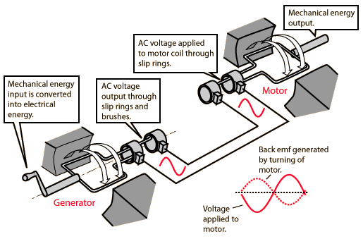
Electrical mechanical energy can be created in one of two ways: using an electric generator or a motor. The concept of electric generator is used to describe a number of devices that convert mechanical energy into electricity. A motor converts electrical energy into mechanical, that is the reverse process of the electrical generator. The energy can be used for a variety of purposes, by a large electric power plant, to be the motor of an electric car use.

It is important to note that there is no such thing as free energy. All energy must be created by something and need a resource. Some type of device is needed to translate the energy from one form to another. For example, solar energy requires the use of solar collectors to trap the sun's rays and convert the heat into electrical energy. This rule applies to electrical and mechanical energy.

An electric generator uses electromagnetic induction to convert mechanical energy into electricity. Mechanical energy is produced by a wind turbine, a hand crank or turbine steam engine. The generator was designed to absorb energy as it is created by the mechanical fastening. The mechanical energy moves the turbine blades, generally against the direction of the magnetic force. This movement generates electromagnetic energy.

The engine is to convert electrical energy into mechanical energy. The electrical energy is produced by the engine, then mechanical energy is created, received by the rotor. This process is the exact opposite of mechanical energy, but has many of the same elements.


Both a generator or motor has a rotor and a stator. A rotor is the actual rotating part of an alternator, generator or motor. The stator is the stationary part, the rotor in position. The anchor is actually produced electric current in the generator and is either built into the rotor or stator. The magnetic field is created by a magnet on the rotor or stator.

Electrical mechanical energy is a common source of power for large power plants and other mechanical equipment. Electrical energy is in high demand, and this constant demand requires the development of new, more efficient forms of exploitation of the electrical mechanical energy. High voltage energy can not be saved, but have available upon request. A career in electrical engineering or mechanical engineering is about the use of this energy source in a variety of designs centered. The positions are devices in electric power generation stations, substations and related.

source:wisegeek.com

What Is Energy Transformation?

Energy transformation is the process of changing energy from one form to another. This process happens all the time, both in the world and in people. When people consume food, the body uses the chemical energy in the bonds of the food and converts it into mechanical energy, a new form of chemical energy or thermal energy. Energy transformation is an important concept in the application of the physical sciences. The possibility for energy are converted automatically, lights, maintains and warms the world in an amazing variety of ways.

The concept of energy transformation can be represented in a number of joint activities. An engine as the engine in a car that converts the chemical energy of gas and oxygen into the mechanical energy of the motor movement. A light bulb changes the chemical energy of the light bulb into electromagnetic radiation or light. Windmills use the power of the wind and convert it into mechanical energy in the movement of the blades, which is then converted into electrical energy. Solar panels convert light into electricity.


Energy transformation, also with respect to potential energy, the stored energy of a system, the kinetic energy in the energy of motion can be converted to be explained. For example, a roller coaster sits on top of a hill have said potential energy. This potential energy is gravity, which is won when the train moves up up the hill. Once the train begins to move down the mountain, is the gravity exerted and move the potential energy into kinetic energy of the car turns. During energy transformations, potential energy is converted into kinetic energy, and often back into potential energy.

While each type of energy transformation, some energy is lost to the environment. As a result of this loss is not a machine, the 100% efficiency. Usually lost a part of the energy in the energy transformation is lost as heat. This may in practice with the finding that the heat generated by a computer, a car or other type of machine that has been in use for a period of time broadcast can be observed.


The ability of a machine or a system to convert between forms of energy as "energy conversion efficiency." All systems have different energy conversion efficiencies. Water turbines, for example, have an extremely high energy conversion efficiency of nearly 90% while internal combustion engines have 10% to 50% efficiency. Engineering and physics are constantly looking for systems that achieve high energy conversion efficiency.

source:wisegeek

Tuesday, March 8, 2011

Distribution Boards

A distribution board (or panelboard) is a component of an electricity supply system which divides an electrical power feed into subsidiary circuits, while providing a protective fuse or circuit breaker for each circuit, in a common enclosure. Normally, a main switch, and in recent boards, one or more Residual-current devices (RCD) or Residual Current Breakers with Overcurrent protection (RCBO), will also be incorporated.

Other names:

Distribution boards are also referred to as a:

  • breaker panel
  • circuit breaker panel
  • consumer unit, or CU
  • electrical panel
  • fusebox
  • fuseboard
  • load centre/center
  • panelboard
  • power breaker
  • service panel
  • DB board (South Africa)

North American breaker panels

The circuit breakers are generally placed in two columns. Circuit breaker panelboards are always dead front, that is, the operator of the circuit breakers cannot contact live electrical parts. During servicing of the distribution board itself, though, when the cover has been removed and the cables are visible, North American breaker panelboards commonly have some live parts exposed.

Breaker arrangement


Illustration of breaker numbering in a North American type panelboard. Some labels are missing, and some lines have additional descriptive labels. The numbers on the toggles indicate the ampereage they will pass before tripping off and stopping all current. The top right breaker (Rated at 100 A) leads to a sub panel.

Breakers are usually arranged in two columns. In a US-style board, breaker positions are numbered left-to-right, along each row from top to bottom. This numbering system is universal across various competing manufacturers of breaker panels.

North American circuit breaker numbering
Split-phase 3-phase Breakers
A A 1 2
B B 3 4
A C 5 6
B A 7 8
A B 9 10
B C 11 12

Each row is fed from a different phase (A, B, and C below), to allow 2- or 3-pole common-trip breakers to have one pole on each phase. In North America, it is common to wire large permanently installed equipment line-to-line. This takes two slots in the panel (two-pole) and gives a voltage of 240V if the supply system is split phase and 208 V if the supply system is three phase.

Inside a North American panel

EEUU(GE)BreakerpanelInnards.jpg

The picture to the right shows the interior of a standard residential service, North American General Electric style breaker panel. The three power lines can be seen coming in at the top (One going to the neutral busbar to the left with all the white wires, the other two attached to the main breaker). Below it are the two rows of circuit breakers with the circuit's hot wire leading off. A line can be seen directly exiting the box and running to a NEMA 5-15 electrical receptacle with a power cord plugged into it.


UK boards

In the UK, domestic and small commercial or public installations usually have single-phase supplies at 230V (nominal standard). The main distribution boards in these installations are called consumer units (CUs), though they may be known as fuse boxes; older consumer units used fuses until the advent of mini-circuit breakers (MCBs).

A consumer unit normally has a single horizontal row of fuses or MCBs, though some older units grouped four fuses in a square arrangement. For two-rate supplies (standard/off-peak), a second CU may be added (stacked). Multiple CUs are also found in larger premises.

Larger commercial, public, and industrial installations generally use three-phase supplies, with distribution boards which have twin vertical rows of breakers. Larger installations will often use subsidiary distribution boards.

In both cases, modern boards handling supplies up to around 100 A (CUs) or 200 A (distribution boards) use circuit breakers and RCDs on DIN rail mountings. The main distribution board in an installation will also normally provide a main switch (known as an incomer) which switches the phase and neutral lines for the whole supply. (n.b., an incomer may be referred to, or sold as, an isolator, but this is problematic, as it will not necessarily be used as an isolator in the strict sense.)

For each phase, power is fed along a busbar. In split-phase panels, separate busbars are fed directly from the incomer, which allows RCDs to be used to protect groups of circuits. Alternatively RCBOs may be used to provide both overcurrent and residual-current protection to single circuits.

Other devices, such as transformers (e.g., for bell circuits) and contactors (relays; e.g., for large motor or heating loads) may also be used.

New British distribution boards generally have the live parts enclosed to IP20, even when the cover has been removed for servicing.


Circuit breaker retrofits

Some of these fuseboxes have had their fuse carriers replaced with plug-in miniature circuit breakers. These retrofit MCBs are typically rated at 3kA breaking capacity, but many homes or properties have prospective short circuit currents as high as 6kA. Fault currents of over 3kA are thus interrupted by the incomer fuse, should they ever occur, and the MCB would not survive.[citation needed]

Historic fuseboxes

A small number of pre-1950 fuseboxes are still in service. These should be treated with caution because exposed live parts are common on these boxes. The installations they supply will not meet modern standards for electrical safety. Another characteristic of very old installations is that there may be two fuses for each circuit; one on the live and one on the neutral. In rare instances, old ring circuits may be encountered with no less than 4 15 A fuses per ring, one on each of L and N, and this duplicated for each of the 2 feeds for the ring.

Inside a UK distribution board

UKDistributionBoard.JPG

This picture shows the interior of a typical 12-position UK distribution panel. The three incoming phase wires connect to the busbars via a main switch in the centre of the panel. On each side of the panel are two busbars, for neutral and earth. The incoming neutral connects to the lower busbar on the right side of the panel, which is in turn connected to the neutral busbar at the top left. The incoming earth wire connects to the lower busbar on the left side of the panel, which is in turn connected to the earth busbar at the top right. The cover has been removed from the lower-right neutral bar; the neutral bar on the left side has its cover in place.

Down the left side of the phase busbars are two two-pole RCBOs and two single-pole breakers, one unused. Down the right side of the busbars are a single-pole breaker, a two-pole RCBO and a three-pole breaker.

The two-pole RCBOs in the picture are not connected across two phases, but have supply-side neutral connections exiting behind the phase busbars.

The illustrated panel includes a great deal of unused space; it is likely that the manufacturer produces 18- and 24-position versions of this panel using the same chassis.

In a UK-style board, breaker positions are numbered top to bottom in the left hand column, then top to bottom in the right column. Each number is used to label one position on each phase, as below, and can be seen faintly in the photograph to the right. It remains to be seen how the new wiring colours recently introduced in the UK will affect this labelling.

Phase Breakers
Red R1 R4
Yellow Y1 Y4
Blue B1 B4
Red R2 R5
Yellow Y2 Y5
Blue B2 B5
Red R3 R6
Yellow Y3 Y6
Blue B3 B6


Manufacturer differences

Most of the time, the panel and the breakers inserted into it must both be from the same company. Each company has one or more "systems", or kinds of breaker panels, that only accept breakers of that type. In Europe this is still the case, despite the adoption of a standard DIN rail for mounting and a standard cut-out shape, as the positions of the busbar connections are not standardised.

Certain panels use seemingly interchangeable 1-inch-wide (25 mm) breakers. However, a given manufacturer will often specify exactly what devices are permitted to be installed in their equipment. These assemblies have been tested and approved for use by a recognized authority. Replacing or adding equipment which "just happens to fit" can result in unexpected or even dangerous conditions. Such installations should not be done without first consulting knowledgeable sources, including manufacturers.

Location and designation


A three phase service drop enters through the rear of this main service panel consisting of three 100 ampere fuses.

For reasons of aesthetics and security, circuit breaker panels are often placed in out-of-the-way closets, attics, garages, or basements, but sometimes they are also featured as part of the aesthetic elements of a building (as an art installation, for example) or where they can be easily accessed. However, current US building codes prohibit installing a panel in a bathroom (or similar room), in closets intended for clothing, or where there is insufficient space for a worker to access it. Specific situations, such as an installation outdoors, in a hazardous environment, or in other out-of-the-ordinary locations may require specialized equipment and more stringent installation practices.

Large buildings or facilities with higher electric power demand may have multiple circuit breaker panels. In this case, the panels are often indicated by letters of the alphabet. One case is The Decon Gallery, a modern building in downtown Toronto, which has 11 breaker panels designated A, B, C, D, and so on. A backstage outlet is therefore labeled C27. In many such buildings, each outlet is on its own circuit breaker, and the outlets are labelled in the above specified manner to facilitate easy location of which breaker to shut off for servicing, rewiring, or the like.

In even larger buildings, such as schools, hospitals and sports/entertainment venues it is not uncommon to have scores of panels, specially designated for each building depending on how the architects and electrical engineers subdivide the building. They are commonly designated as either three-phase or single-phase and normal power or emergency power. In these set-ups they may also be designated for their use, such as distribution panels for supplying other panels, lighting panels for lights, power panels for equipment and receptacles and special uses for whatever type of building they are used in. It is also not uncommon for these panels to be located throughout the building in electric closets serving a section of the building.

In a theatre a specialty panel called a dimmer rack is used to feed stage lighting instruments. A US style dimmer rack has a 208Y/120 volt 3-phase feed. Instead of just circuit breakers, the rack has a solid state electronic dimmer with its own circuit breaker for each stage circuit. This is known as a dimmer-per-circuit arrangement. The dimmers are equally divided across the three incoming phases. In a 96 dimmer rack, there are 32 dimmers on phase A, 32 dimmers on phase B, and 32 on phase C to spread out the lighting load as equally as possible. In addition to the power feed from the supply transformer in the building, a control cable from the lighting desk carries information to the dimmers in a control protocol such as DMX-512. The information includes commands on levels, fade times, and which dimmers come up and go out during the lighting changes of the show (light cues).

Distribution boards may be surface-mounted on a wall or may be sunk into the wall. The former arrangement allows for easier alteration or addition to wiring at a later date, but the latter arrangement may look neater, particularly in a residential situation. The other problem with recessing a distribution board into a wall is that if the wall is solid a lot of brick or block may need to be removed - for this reason recessed boards are generally only fitted on new-build projects when the required space can be built into the wall.

Mobile operation

Breakerpanel-mechroom136rp.jpg

Sometimes it is desired to have a portable breaker panel, for example, for special events. In this case, a breaker panel is mounted to a board, together with various sockets. The American one pictured at the right has a cord with an L21-30 plug to supply power. Power leaves the board through four three-phase circuits: three 15 ampere circuits; and one 20 A circuit. The 15 A circuits each go to a triplex-box. The 20 A circuit goes to an L21-20 receptacle, and one leg of it goes to a 20 A duplex receptacle shown at the upper left. The neon night-lights on the upper right triplex box are to show the phase presence.

The use of a load center in this type of configuration is dangerous and violates UL and NEC rules for their use. When power distribution is required on movie sets, concert stages and theatrical venues it should be provided via products Listed "for portable power distribution."


Read more:en.wikipedia.org

Monday, February 28, 2011

What is Electrical Engineering?

Electrical engineering is a field of engineering that deals generally with the analysis and application of electricity, electronics and electromagnetism. The field was first an identifiable occupation in the late nineteenth century after commercialization of the electric telegraph and power supply. It now covers a number of sub-themes including energy, electronics, control engineering, signal processing and telecommunications.

Electrical Engineering Electrical Engineering can. If a distinction is made, usually outside the United States, the electrical engineering as the problems with large electrical systems such as powertrain and engine control them, while electrical engineering is concerned with the study of small electronic systems deal including computers and integrated circuits. Alternatively, electrical engineers are usually transferred with the help of electricity and energy, while electronics engineers concerned concerned with using electricity, information is processed. In recent times become blurred the distinction by the growth of power electronics.

History

Main article: History of Electrical Engineering
The discoveries of Michael Faraday were the basis of the electric motor technology.

Electricity is a subject of scientific interest since at least the early 17th Century. The first electrical engineer was probably William Gilbert who designed the versorium: a device that detected the presence of statically charged objects. He was also the first to draw a clear distinction between magnetism and static electricity and credited with establishing the term electricity. In 1775, Alessandro Volta invented Electrophorus scientific experiments, a device that generates a static electric charge, and by 1800 Volta developed the voltaic pile, a forerunner of the electric battery .

However, it was not until the 19th Century that research began to delve into the topic. Notable developments in this century include the work of Georg Ohm, which quantifies in 1827, the ratio between the electric current and potential difference in a conductor, Michael Faraday, the discoverer of electromagnetic induction in 1831, and James Clerk Maxwell, who in 1873 published a unified theory of electricity and magnetism in his treatise Electricity and Magnetism.
Thomas Edison built the world's first large-scale electrical supply network.

In these years, the study of electricity largely as a branch of physics. Only at the end of the 19th Century that the universities that offer degree courses started in electrical engineering. The Technical University of Darmstadt, founded the first chair and the first faculty of electrical engineering worldwide in 1882. In the same year, under Professor Charles Cross, began the Massachusetts Institute of Technology offers the first option in a Department of Electrical Engineering Physics . In 1883 Darmstadt University of Technology and Cornell University introduced the world's first degrees in electrical engineering and in 1885 the University College London founded the first Department of Electrical Engineering in the United Kingdom. The University of Missouri later became the first faculty of electrical engineering in the United States in 1886 .

Nikola Tesla Long-distance electrical transmission networks possible.

During this period, the work increased dramatically in the field of electrical engineering. In 1882, Edison switched on the world's first large-scale electrical supply network that provided 110 volts direct current to fifty-nine customers in Lower Manhattan is available. In 1884 Sir Charles Parsons invented the steam turbine, which now generates about 80 percent of electric energy in the world with a variety of heat sources. In 1887 Nikola Tesla filed a number of known patents related to a competing form of power distribution as alternating current. In the following years a bitter rivalry between Tesla and Edison, as the "war of currents', and took over the preferred method of distribution. AC eventually replaced DC for generation and power distribution to the enormous range and improving the safety and efficiency of power distribution.

The efforts of the two has a lot to work on electrical engineering-Tesla induction motors and polyphase systems influenced the field for years to come, while Edison proved to work telegraphy and his development of the stock ticker lucrative for his company, which ultimately was General Electric. But by the end of the 19th Century, other key figures in the progress of electrical engineering is beginning to emerge.

Modern developments

During the development of radio, contributed many scientists and inventors, radio engineering and electronics. In his classic UHF experiments of 1888, Heinrich Hertz transmitted (via a spark gap transmitter) and detected radio waves using electrical equipment. In 1895 Nikola Tesla was able to detect signals from the transmissions of his New York lab at West Point (a distance of 80.4 km / 49.95 miles). In 1897, Karl Ferdinand Braun introduced the cathode ray tube as part of an oscilloscope, a crucial enabling technology for electronic television. John Fleming invented the first radio tube, the diode, in 1904. Two years later, Robert von Lieben and Lee De Forest independently developed the amplifier tube, called the triode. In 1895, Guglielmo Marconi promoted the art of Hertz's wireless methods. Early on he radio signals over a distance of one and a half miles. In December 1901 he sent radio waves, which were not affected by the curvature of the earth. Marconi later transmitted the wireless signals across the Atlantic between Poldhu, Cornwall, and St. John's, Newfoundland, a distance of 2,100 miles (3400 km). In 1920 Albert Hull developed the magnetron which would eventually lead to the development of the microwave in 1946, Percy Spencer of the oven. In 1934 the British military on track radar (which also uses the magnetron) under the direction of making Dr. Wimperis began, culminating in the operation of the first radar station at Bawdsey in August 1936 .

In 1941 Konrad Zuse presented the Z3, the world's first fully functional, programmable computer. In 1946, ENIAC (Electronic Numerical Integrator and Computer) by John Eckert and John Mauchly Presper followed in the early computing era. The computing power of machines allowed engineers to develop entirely new technologies and achieve new goals, including the Apollo missions of NASA and the moon landing.

The invention of the transistor in 1947, opened by William B. Shockley, John Bardeen and Walter Brattain the door for more compact devices and led to the development of the integrated circuit in 1958 by Jack Kilby and independently in 1959 by Robert Noyce . Beginning in 1968, Ted Hoff invented and a team at Intel's first commercial microprocessor, which announced the personal computer. The Intel 4004 was released a 4-bit processor in 1971, but in 1973 the Intel 8080, an 8-bit processor, made the first personal computer, the Altair 8800, possible.

Education:

Main article: Education and Training Electrical and Electronics Engineers

Electrical engineers typically possess an academic degree with an emphasis on electrical engineering. The length of study for such a level is completed usually four or five years and the final will be designated as Bachelor of Engineering, Bachelor of Science, Bachelor of Technology or Bachelor of Applied Science in function of the university. The degree usually includes units for physics, mathematics, computer science, project management and special topics in electrical engineering. Initially such topics cover most, if not all, of the disciplines of electrical engineering. Students then select one or more sub-disciplines towards the end of study to specialize.

Some electrical engineers also the possibility of further study as a Master of Engineering / Master of Science (M. Eng. / M.Sc.), A Master of Engineering Management, a Doctor of Philosophy (Ph.D.) in pursuing engineering, an Engineering Doctorate (Eng.D.), or an engineering degree. The Master and Engineer's degree may consist of either research, study or a mixture of both. The Doctor of Philosophy and Engineering Doctorate degrees consist of a significant research component and are often seen as the entry point into the science. In the United Kingdom and several other European countries, the Master of Engineering is often considered an undergraduate degree of slightly longer duration than the Bachelor of Engineering.

Source:wikipedia.org

Sunday, February 20, 2011

What is Solar Thermal Energy?

Solar thermal is a form of energy in the sun to heat, which can produce are used in many ways. People have been using solar thermal energy for thousands of years for a variety of tasks, and modern technology has expanded the applications for solar thermal energy. This should not be using solar energy, which used the light from the sun to be mixed to produce electrical energy.

Some of the applications for solar thermal systems are very old. For example, the solar drying is a technique, the heat from the sun in food preservation. In this application, foods are placed on rocks, and the warmth of the sun is used to dry them. Evaporation ponds, as they are used to concentrate salt also use solar energy and desalination plants can also apply this energy.


This form of energy can also be used for cooking, sometimes in very creative ways. Solar ovens use solar thermal and solar thermal energy can be used to heat water to generate steam for cooking. Pasteurization can be achieved with the use of concentrated heat from the sun. Another use of this type of energy is used in the distillation of liquids, and of course in hot water heating. Water heated by solar thermal energy can be used for bathing, cleaning and cooking. It can also be used for home heating, hot water can be distributed as under a floor, to warm them.


Solar thermal can also be used for cooling, although it sounds paradoxical to use heat to cool, things. In this application it is in a process as evaporative cooling, which can keep the cooling of buildings known uses. All of these applications for the warmth of the sun can for beginners and advanced, for people in the communities around the world, including the communities in developing countries.

Finally, heat can be used from the sun to generate electricity. This requires some extensive support technology, but an advantage is that since the heat can be stored, a solar thermal system can work to fulfill 24 hours a day to power. These facilities are usually in areas located get much sun, so that the maximum amount to be used in thermal solar energy. Towers and reflective arrays of different kinds can be used, to collect the sun's heat and concentrate it for the purpose of generating electricity.

Monday, February 7, 2011

Simple LED Flashlight Explained

A commercially available, inexpensive mini-LED flashlight can typically from a white LED, a couple of button cells and a switch mechanism exist. Such a sample has been diagnosed here. The studied sample can be easily copied and built by anyone under ordinary technical skills.

LEDs were invented before, only the incandescent light-emitting devices that could be used easily and cheaply in flashlights. Although even now like torches are in use, but light bulbs, as we all know, pretty inefficient power consumption require frequent battery replacement and thus ultimately like torches are expensive to maintain and run.

With the advent of modern improved high-efficiency white LEDs, producing dazzling lights with negligible power become possible now, and burning torches slowly obsolete. LED flashlights are in fact so efficient that it can take batteries almost forever, so that they produce amazing light effects devices.

White LEDs built in lenses and can therefore no additional reflectors, which adds to their efficiency in the creation of sharp light pattern, however, the introduction of external parabolic mirror amplifies the light many folds and is, therefore, LED flashlights, the near eye-blinding Date produce illumination by ordinary power inputs.

In this article we will try to understand the electrical and mechanical details of a commercially available LED flashlight. Let us learn the rather simple structure of such a sample.
Simple internal configurations

A glowing LED is actually very simple because it does not contain much in the way of technical or electronic skills.

simply by connecting an LED's anode and cathode terminals to a power source, the LED lights are bright.

However, this is a criterion that must be strictly followed with LEDs, that the supply voltage must never much of its voltage drop, which may be different for different LEDs (colors.)
Mini LED flashlight cicuit, chart, picture

For example, the forward voltage of white LEDs around 3.6 volts, exceed the applied voltage should not be 4 volts (ideally), but have said that higher input voltages must be included only if the LED according to a calculated resistance is connected in series.

The next picture shows a mini LED flashlight, small prices (you can buy only 7 of them for a dollar) on the market, making it also a "use and throw" type of device. It basically operated from a single white LEDs from three tiny button cells in series.

Mini LED flashlight, LED flashlight mini image, image, mini LED torch, mini flashlight image, image

Because each cell produces a voltage of 1.5 volts, three of them stacked into a beautiful 4.5 volts, just perfect for the supply of a single white LEDs give very bright (the picture shows that simple.)

The dissected view of the burner, the following steps, which are easily copied and can even be built by an electronic beginners:

The electrical part of this LED flashlight consists essentially of an LED and arranged three button cells in series, ie the negative of the upper cell contacts the positive of the second cell and the negative of the second cell, the positive of the third cell affected, so that the positive of the first and the negative of the third cell free, so it leads to the LED over.

The cathode of the LED is fixed to the negative of the cell assembly is connected, while the anode to the positive voltage source through a strip of brass, positioned so that it is like a leaf switch "plot twist, the LED OFF switch in response to the sliding door ( with the fingers) of an external mechanism.

The concept for innovative applications:

LEDs on a Frisbee, ImageLED Car Roof Light diagram ImageAs already discussed to wire LEDs fairly simple, a number of interesting extensions small light may be using a few or many LEDs and a battery or assessed according to a voltage source.

For example, as can be joined together as shown to make a nice little top light for your car interior in the figure six LEDs. The positive of the circuit can be connected through the switch door, so that the LEDs light up immediately after opening one of the doors. By adding a capacitor, it can be the lights in order for a few more seconds, even after the doors closed and the switches are turned off.

Another application that would definitely impress your friends is attaching a couple of LEDs to a normal Frisbee. You can by drilling a few holes at regular Frisbee and setting LEDs in them, which would then be supplied by button cells, as illustrated in the accompanying diagrams with power.

source:brighthub.com